| Issue |
Wuhan Univ. J. Nat. Sci.
Volume 27, Number 3, June 2022
|
|
|---|---|---|
| Page(s) | 261 - 264 | |
| DOI | https://doi.org/10.1051/wujns/2022273261 | |
| Published online | 24 August 2022 | |
Information Technology
CLC number: TN 75
An Electrical-Variable-Frequency Compact Wien-Bridge Oscillator
1
School of Information Engineering, Shaanxi Institute of International Trade & Commerce, Xi'an
712046, Shaanxi, China
2
School of Physics and Electronic Engineering, Xianyang Normal University, Xianyang
712000, Shaanxi, China
Received:
7
April
2022
This paper designs a current-mode Wien-bridge oscillator to use current-controlled conveyor (CCCIIs) based on the traditional Wien-bridge oscillator and the adjoint network theorem. This oscillator employs only four CCCIIs and two grounded capacitors. Its resonant condition and resonant frequency can be independently and electronically varied by tuning bias currents of the CCCIIs linearly. Then this oscillator is simple in design, compact in size, and convenient in adjustment. The oscillator analysis and computer simulation results have been included to support the generation method.
Key words: Wien-bridge oscillator / orthogonal electronic control / current-mode circuit / second generation current-controlled conveyor(CCCIIs) / adjoint network theorem
Biography: LI Yongan, male, Professor, research direction: analog signal processing circuits and current-mode circuits. E-mail: lya6189@sohu.com
Foundation item: Supported by the Natural Science Foundation of Shaanxi Province (2017JM6087)
© Wuhan University 2022
 This is an Open Access article distributed under the terms of the Creative Commons Attribution License (https://creativecommons.org/licenses/by/4.0), which permits unrestricted use, distribution, and reproduction in any medium, provided the original work is properly cited.
0 Introduction
The Wien-bridge oscillator is one of the most typical oscillators used in audio and sub-audio frequency ranges, which has been found wide applications in linear and nonlinear circuits[1]. The Wien-bridge oscillator employing the operation amplifier (Op Amp) is a simple and practical circuit, but it is a voltage-mode circuit rather than a current-mode circuit[2]. Though the Wien-bridge oscillator using the current conveyor (CCII) is a typical current-mode circuit, its parameter cannot be adjusted electronically[3]. The Wien-bridge oscillator using the operation transconductance amplifier (OTA) enjoys simple structure and electronic tunability, but it is not a true current-mode circuit because the inputs of the OTA are voltages rather than currents[4]. The Wien-bridge oscillator proposed by Fabre et al [5] can exhibit good performances. However, it suffers from either the use of the floating capacitor or the use of the transconductance mode circuit due to the used OTA.
On the other hand, the second generation current-controlled conveyor (CCCII) employing the bipolar technology was first introduced by Fabre et al in 1996[5]. Since then, many current-mode circuits based on CCCII, like the analog filters, oscillators, and gyrator circuits, have been investigated, which shows that the CCCII is a very interesting current-mode device. In spite of the fact that oscillators using CCCIIs have been widely reported[6-14], they are neither Wien-bridge oscillators, nor oscillators with orthogonal adjustment between the resonant frequency and resonant condition. Literature survey shows the CCCII scillators using the traditional Wien-bridge oscillator rather than the grounded-capacitor Wien-bridge oscillator as topology have rarely been reported so far.
In this paper, a current-mode Wien-bridge oscillator employing the CCCII is designed, which utilizes the traditional Wien-bridge oscillator and the adjoint network theory and contains four CCCIIs and two grounded capacitors. Its resonant condition and resonant frequency can be independently and electronically varied by tuning bias currents of the CCCIIs linearly. From the perspective of selectivity, grounding capacitance, and the simplest structure, this oscillator is the simplest, most economical and least distortion circuit. The results from circuit simulation are in agreement with theory.
1 Design
The traditional Wien-bridge oscillator employing single Op Amp reported in Ref. [2] is shown in Fig. 1. This circuit consists of an Op Amp connected in a non-inverting amplifier and a lead-lag network connected as the feedback circuit. It is customary to impose C 1=C 2=C, R 1=R 2=R, after which the gain of the non-inverting amplifier, the feedback coefficient of the positive feedback network, and the loop gain can be readily calculated as


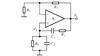 |
Fig. 1 Traditional Wien-bridge oscillator using Op Amp |
The resonant condition (including start-up condition) and resonant frequency for the oscillator have been given by

This is the already-familiar conclusion.
The grounded-capacitor Wien-bridge oscillator using an Op Amp has been reported in Ref. [3]. This circuit can be viewed as a non-inverting amplifier with frequency-dependent gain and a positive frequency-selecting feedback network. When C 1=C 2=C, R 1=R 2=R, the gain of the non-inverting amplifier, the feedback coefficient of the positive feedback network, and the loop gain can be readily calculated as


Substituting (7) into the characteristic equation, 1-A u F u=0, we find that the resonant condition and resonant frequency are the same as Eq. (4), showing that although the series and parallel combination of RC is separated, the circuit still belongs to a member of Wien-bridge oscillator family. However, unlike the traditional Wien-bridge oscillator, the loop gain of the grounded-capacitor Wien-bridge oscillator, from (7), is not a band-pass function but a combination of the band-pass function and low-pass function. This could not guarantee that the circuit enjoys less distortion. Consequently, from a selective visual perspective, the traditional Wien-bridge oscillator is superior to the grounded-capacitor Wien-bridge oscillator.
To achieve the grounded-oscillator current-mode oscillator, we need to transform the lead-lag network of Fig. 1 into an adjoint network by the adjoint network theory, as depicted in Fig. 2. According to the adjoint network theory, we can easily find

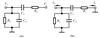 |
Fig. 2 Lead-lag network of Fig. 1 (a) RC series and parallel network; (b) Adjoint network of (a) |
Here, C 1=C 2=C, R 1=R 2=R.
Figure 3 shows a current-mode oscillator based on Fig. 2(b), where CCCII3 and CCCII4 form the non-inverting current amplifier with gain greater than unity:

 |
Fig. 3 Designed oscillator with CCCII1 serving a floating resistor R 1 and CCCII2 serving a grounded resistor R 2 |
where Rx 3=V T/2I B3, Rx 4=V T/2I B4, I B3 and I B4 are bias currents of CCCII3 and CCCII4, respectively, and V T represents the thermal voltage that is 26 mV at room temperature.
CCCII1, CCCII2, C 1, and C 2 in Fig. 3 create the positive feedback network to form the feedback coefficient depicted by (8). Substituting (8) and (9) into the characteristic equation of the oscillator, 1-AiFi =0, we get

where R
 =R
=R
 1=R
1=R
 2=V
T/2I
B, and I
B is the bias current of CCCII1 or CCCII2.
2=V
T/2I
B, and I
B is the bias current of CCCII1 or CCCII2.
The resonant condition (including start-up condition) and resonant frequency are then


(11) and (12) show that the linear, independent and electronic control of the resonant frequency and resonant condition can be realized as follows; a) tune I B3 or I B4 to adjust to the resonant condition, not influencing resonant frequency; b) tune I B to adjust to the resonant frequency, not influencing resonant condition. (11) and (12) also show that orthogonal electronic control must require four parameters, namely I B3, I B4, I B1, and I B2 (I B1=I B2), so the oscillator needs at least four CCCIIs.
Under sinusoidal steady-state conditions, from Fig.3, we can easily get

(13) denotes that the designed oscillator can generate two sinusoidal signals with the same frequency, same phase, and amplitude difference of two times.
2 Verification
To start with, the sub-circuit for a CCCII was established by the transistor model of PR200N and NR200N of the analog device library from NI MULTISIM 11.0 software[15]. Then the circuit in Fig. 3 was simulated by using ±2.5 V power supplies. When I B3=12 µA, I B4=5 µA, then Eq. (11) is satisfied. If setting C 1=C 2=100 pF, I B=5 µA, the design value for f o from (12) is 612 kHz. The simulation results are shown in Fig. 4, which shows that the actual values for f o is 568 kHz. The relative error is then -7.2%. I o2/I o1 is about 2.
 |
Fig. 4 Initial results of the transient analysis for Fig. 3 |
When I B is varied from 5 µA to 25 µA and 50 µA, and I B3 and I B4 stay the same, the design value for f o is adjusted from 612 kHz to 306 kHz and 6.12 MHz, respectively (Fig. 5). Therefore, the controllability of f o by adjusting I B is realized. Cursor measurements show that the actual values for f o is 5.84 MHz when I B is 50 µA. The relative error is then -4.6%.
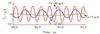 |
Fig. 5 Relationship of resonant frequency and I B |
Cursor measurements show that the total harmonic distortions for I o1 and I o2 are 0.86% and 1.02%, respectively. Figure 6 shows only the simulated output spectrum for I o1. In the output waveform, the even-order harmonic components are much lower than the odd-order harmonics due to the fact that the output is positive and negative symmetrical waveforms because of limitations from the output saturation. Consequently, the oscillator can produce two output signals with small distortion.
 |
Fig. 6 Output spectrum of I o1 for the design value of f o=612 kHz |
The power consumed by the oscillator is about 3.10 mW. There is no doubt that the simulation results are consistent with the applied theory.
3 Conclusion
The existing current-mode Wien-bridge oscillators using a variety of new types of active devices employ either the grounded-capacitor Wien-bridge oscillator or the traditional Wien-bridge oscillator. The former must use grounded capacitors, which is easy to integrate but has poor selectivity, while the latter must use a floating capacitor, which has good selectivity but is not easy to integrate. So far the current-mode Wien-bridge oscillators using the traditional Wien-bridge oscillator as topology and using grounded capacitors have not been developed, so this is the first paper to give the answer to this question. In addition, the designed oscillator enjoys the following features: orthogonal electronic control of resonant condition and resonant frequency, use of grounded capacitors, good selectivity of frequencies, no externally connected resistors and high output impedances.
References
- Elwy O, Said L A, Madian A H, et al. All possible topologies of the fractional-order Wien oscillator family using different approximation techniques [J]. Circuits, Systems, and Signal Processing, 2019, 38(9): 3931-3951. [CrossRef] [Google Scholar]
- Budak A. Passive and Active Network Analysis and Synthesis [M]. Long Grove: Waveland Press Inc, 1991. [Google Scholar]
- Soliman A M. Generation of CCII and ICCII based Wien oscillators using nodal admittance matrix expansion [J]. AEU-International Journal of Electronics and Communications, 2010, 64(10): 971-977. [Google Scholar]
- Li Y A. Synthesis of compact VDTA-based Wien oscillators with grounded capacitors [J]. AEU-International Journal of Electronics and Communications, 2018, 84: 281-289. [Google Scholar]
- Fabre A, Saaid O, Wiest F, et al. High frequency applications based on a new current controlled conveyor [J]. IEEE Transactions on Circuits and Systems I Fundamental Theory and Applications, 1996, 43(2): 82-91. [CrossRef] [Google Scholar]
- Kiranon W, Kesorn J, Wardkein P. Current controlled oscillator based on translinear conveyors [J]. Electronics Letters, 1996, 32(15): 1330-1331. [NASA ADS] [CrossRef] [Google Scholar]
- Kiranon W, Kesorn J, Sangpisit W, et al. Electronically tunable multi-functional translinear-C filter and oscillator [J]. Electronics Letters, 1997, 33(7): 573-574. [NASA ADS] [CrossRef] [Google Scholar]
- Li Y A. RC oscillators based on high-Q frequency-selecting network [J]. IET Circuits, Devices & Systems, 2018, 12(1): 82-87. [CrossRef] [Google Scholar]
- Appala-Naidu G, Mounika S, Krishna B T. Implementation of RC oscillator with high-Q frequency selection using CCCII [J]. International Journal of Innovative Technology and Exploring Engineering, 2019, 8(4): 4470-4477. [CrossRef] [Google Scholar]
- Li Y A. Synthesis for current-mode sallen-key filter using VDTAs [J]. Wuhan University Journal of Natural Sciences, 2020, 25(5): 428-434. [Google Scholar]
- Li Y A, Hou J Q. Pathological models of EXCCCII and its applications in oscillator synthesis [J]. Wuhan University Journal of Natural Sciences, 2021, 26(1): 115-122. [Google Scholar]
- Li Y A, Chen B. Systematic synthesis for multiple-feedback filter using OTAs and CCCIIs [J]. Wuhan University Journal of Natural Sciences, 2020, 25(1): 71-77. [Google Scholar]
- Li Y A, Chen B. Systematic synthesis for electronic-control colpitts oscillator using CCCIIs [J]. Wuhan University Journal of Natural Sciences, 2019, 24(3): 251-256. [CrossRef] [Google Scholar]
- Agrawal D, Maheshwari S. High-performance electronically tunable analog filter using a single EX-CCCII [J]. Circuits, Systems, and Signal Processing, 2021, 40(3): 1127-1151. [CrossRef] [Google Scholar]
- Siripruchyanun M, Jaikla W. Current controlled current conveyor transconductance amplifier (CCCCTA): A building block for analog signal processing [J]. Electrical Engineering, 2008, 90(6): 443-453. [CrossRef] [Google Scholar]
All Figures
|
Fig. 1 Traditional Wien-bridge oscillator using Op Amp |
| In the text | |
|
Fig. 2 Lead-lag network of Fig. 1 (a) RC series and parallel network; (b) Adjoint network of (a) |
| In the text | |
|
Fig. 3 Designed oscillator with CCCII1 serving a floating resistor R 1 and CCCII2 serving a grounded resistor R 2 |
| In the text | |
|
Fig. 4 Initial results of the transient analysis for Fig. 3 |
| In the text | |
|
Fig. 5 Relationship of resonant frequency and I B |
| In the text | |
|
Fig. 6 Output spectrum of I o1 for the design value of f o=612 kHz |
| In the text | |
Current usage metrics show cumulative count of Article Views (full-text article views including HTML views, PDF and ePub downloads, according to the available data) and Abstracts Views on Vision4Press platform.
Data correspond to usage on the plateform after 2015. The current usage metrics is available 48-96 hours after online publication and is updated daily on week days.
Initial download of the metrics may take a while.