| Issue |
Wuhan Univ. J. Nat. Sci.
Volume 31, Number 1, February 2026
|
|
|---|---|---|
| Page(s) | 79 - 90 | |
| DOI | https://doi.org/10.1051/wujns/2026311079 | |
| Published online | 06 March 2026 | |
Computer Applications and Software
CLC number: TP391.41
An Intelligent Sorting System of Coal-Gangue Based on Machine Vision and Convolutional Neural Network
一种基于机器视觉与卷积神经网络的煤矸智能分拣系统
1
College of Physics and Electronic Engineering, Huaibei Normal University, Huaibei 235000, Jiangsu, China
(淮北师范大学 物理与电子工程学院,安徽 淮北 235000)
2
Anhui Province Key Laboratory of Intelligent Computing and Applications, Huaibei Normal University, Huaibei 235000, Jiangsu, China
(淮北师范大学 智能计算及应用安徽省重点实验室,安徽 淮北 235000)
3
Internet of Things (Sensing Mine) Research Center, China University of Mining and Technology, Xuzhou 221116, Jiangsu, China
(中国矿业大学 物联网(感知矿山)研究中心,江苏 徐州 221116)
† Corresponding author. E-mail: This email address is being protected from spambots. You need JavaScript enabled to view it.
Received:
25
March
2025
Abstract
Gangue is inevitably mixed with coal during mining and transportation. Currently, the manual sorting and conventional mechanical separation technologies widely adopted in the coal mining industry are plagued by low efficiency, poor identification accuracy, severe environmental pollution, and other drawbacks. This paper proposes a machine vision-based intelligent coal gangue sorting robot system. Firstly, the OpenMV captures images of coal gangue and utilizes the MobileNetV2 0.35 lightweight convolutional neural network to train the FOMO (Faster Objects, More Objects) target detection model in the cloud. This enables prediction and recognition of gangue, along with the acquisition of its center point pixel coordinates. Secondly, the position information of the gangue is sent to the STM32 microcontroller using the serial communication protocol for coordinate system conversion, pose algorithm, and path planning. Finally, the STM32 microcontroller controls the start and stop of the conveyor belt through the working status of the relay. When the relay is absorbed, the conveyor belt stops, and at the same time, the robotic arm grasps the gangue for transfer action, thus realizing the sorting of coal and gangue. The experimental results demonstrate that the cloud-trained FOMO neural network model achieves an F1 score of 95.5% and a recall of 91.3%, with a test accuracy of 97.56%. The quantified model deployed on OpenMV can accurately identify multiple gangues and output their position information. The success rate of the robotic arm in tracking and sorting gangue reaches 90.13%, and the positioning error of the robotic arm is [9,12.5] mm. This system realizes high-precision identification, positioning, and intelligent sorting of coal and gangue, meeting the basic requirements for gangue sorting in coal mines.
摘要
煤矿开采和运输煤炭过程中通常掺杂矸石,当前煤矿行业常用的人工和传统机械分拣方式普遍存在效率低下、识别精度低、环境污染严重等问题。本文提出了一种基于机器视觉的智能煤矸分拣机器人系统。首先,通过OpenMV采集煤矸图像,利用MobileNetV2 0.35轻量级卷积神经网络在云端训练FOMO(Faster Objects, More Objects)目标检测模型,对矸石进行预测识别并获取中心点像素坐标;其次,采用串口通信的协议方式将矸石位置信息发送到STM32单片机,进行坐标系转换、姿态解算和路径规划;最后,STM32单片机通过继电器的工作状态控制传送带启停,当继电器吸合时传送带停止,同时机械臂对矸石进行抓取转运动作,实现煤和矸石的分拣。实验结果表明:云端训练FOMO神经网络模型得出F1分数为95.5%,召回率91.3%,模型测试结果准确度为97.56%,部署到OpenMV中可以较为准确地识别出多个矸石并且输出其位置信息,机械臂跟踪分拣矸石的成功率达90.13%,机械臂定位误差在[9,12.5]mm,实现煤和矸石的高精度识别、定位和智能分选,满足煤矿煤矸分拣的基本要求。
Key words: coal-gangue recognition / intelligent sorting / lightweight / FOMO (Faster Objects, More Objects) model / path planning
关键字 : 煤矸识别 / 智能分拣 / 轻量级 / FOMO(Faster Objects, More Objects)模型 / 路径规划
Cite this article:MIAO Shuguang, ZHANG Qiuyue, GUO Mengxu, et al. An Intelligent Sorting System of Coal-Gangue Based on Machine Vision and Convolutional Neural Network[J]. Wuhan Univ J of Nat Sci, 2026, 31(1): 79-90.
Biography: MIAO Shuguang, male, Ph.D., Associate professor, research direction: mine internet of things, embedded systems and application. E-mail: This email address is being protected from spambots. You need JavaScript enabled to view it.
Foundation item: Supported by the National Natural Science Foundation of China (52074273), Natural Science Research Project of Universities in Anhui Province (2023AH050343), Anhui Innovative Team for Pollutant Sensitive Monitoring and Application (2023AH010043), Anhui Province Graduate Education Quality Project (2024jyjxggyjY204), Innovation and Entrepreneurship Training Programme for College Students in Anhui Province(S202410373037), Huaibei Normal University’s Postgraduate Education Quality Project (2024jgxm003), Open Project Funded by Anhui Province Key Laboratoryof Intelligent Computing and Applications (AFZNJS2025KF08)
© Wuhan University 2026
 This is an Open Access article distributed under the terms of the Creative Commons Attribution License (https://creativecommons.org/licenses/by/4.0), which permits unrestricted use, distribution, and reproduction in any medium, provided the original work is properly cited.
0 Introduction
China is the largest coal producer in the world, and the green mining, efficient and intelligent utilization of coal resources are crucial to national development[1]. In the process of coal mining, raw coal is mixed with gangue accompanying the coal seam, which is a type of solid waste with low calorific value, high water content, and high impurity content[2]. Due to its relatively high content of sulfur dioxide and other harmful substances, gangue causes environmental pollution to rivers, atmosphere, and soil. Therefore, gangue sorting is particularly important in the field of coal mining. Presently, the primary coal gangue sorting methods employed in China are manual gangue sorting and mechanical gangue separation. Manual gangue sorting is plagued by low sorting efficiency, poor working conditions, high labor intensity, and high costs. Traditional mechanical gangue separation methods generally suffer from low identification accuracy, large floor space, high investment costs, and severe environmental pollution, failing to meet the requirements of green manufacturing[3].
Coal mine intelligence serves as the core technical support for adapting to the development direction of the modern industrial technology revolution, safeguarding national energy security, and promoting the high-quality development of the coal industry[4-6]. In recent years, to align with the trend of gangue sorting technology toward automation and intelligence, the main methods commonly used in non-contact gangue identification include infrared thermal imaging identification[7], electromagnetic wave identification[8], reflectance spectral identification[9], ultrasonic identification[10], vibration signal identification[11], and image recognition[12]. Among these, image recognition combined with machine vision technology, leveraging its advantages of high intelligence and safety reliability, has been widely applied in coal-rock interface identification, dry coal beneficiation, and conveyor belt speed regulation, driving the automation and intelligent advancement of the coal gangue separation process. In practical applications, Shang et al[13] adopted Support Vector Machines (SVM) for coal gangue image recognition and verified the feasibility of the coal gangue sorting platform. Cao’s team[14] utilized transfer learning methods to extract classification information and spatial coordinates from coal gangue images, achieving an identification accuracy of 90.17%. They also investigated the impact of different belt speeds on the system’s recognition performance, providing a case study for intelligent coal mining. Hu et al[15] proposed a two-stage object detection network combining YOLOv2 and AlexNet for coal gangue image identification and realized intelligent coal gangue sorting using a specially developed sorting device, though the sorting efficiency still needs improvement. Pang et al[16] improved the SVM through the Particle Swarm Optimization (PSO) algorithm, enabling effective distinction of characteristic information between coal and gangue. Li et al[17] designed the ResNet18-YOLOv3 algorithm and constructed an experimental platform for coal gangue sorting robots; through testing with the coal gangue sorting system, an accuracy rate of 82% was achieved. However, most of the aforementioned studies have focused on algorithm optimization. While recognition accuracy has been enhanced, the approach remains plagued by inherent limitations, including high hardware costs and bulky device form factors. These limitations pose significant challenges to its deployment on resource-constrained embedded platforms.
To address the aforementioned issues, this study designs an intelligent coal-gangue sorting system based on machine vision and convolutional neural network. In this system, coal and gangue are placed on a conveyor belt, which transports them to the detection area. An OpenMV camera captures images of the coal and gangue to identify and locate the gangue, and the gangue location information is sent to the STM32 microcontroller via serial communication. When the STM32 receives the gangue location information, the relay is activated, the conveyor belt stops, and the robotic arm is then controlled to act, grab the gangue, and transfer it, ultimately completing the automatic sorting of coal and gangue. This machine vision-based sorting method can realize real-time identification and classification of coal and gangue, improving sorting speed and accuracy. It not only reduces labor costs and energy consumption but also plays a positive role in environmental protection and sustainable development.
1 Overall Design of the System
The system comprises a computer, an OpenMV camera, a robotic arm, an STM32 microcontroller, a conveyor belt, relays, and detection objects (coal and gangue). The system framework diagram is shown in Fig. 1.
 |
Fig. 1 System frame diagram |
The primary design ideas of the system are as follows: Firstly, a simulated coal gangue sorting platform is constructed in the laboratory. Secondly, the gangue image data is collected to produce a sample dataset, and a detection model is built using a deep learning network for target object recognition and localization. Finally, the combination of the STM32 microcontroller and the relay module is used to control the robotic arm to perform the gangue gripping function. The system is capable of real-time online identification, positioning, and intelligent sorting of coal gangue based on machine vision. It has established a collaborative architecture between lightweight deep learning and embedded hardware. The model is efficiently deployed to OpenMV, achieving a coal gangue identification accuracy rate of 97.56%. Combined with microcontroller unit (MCU) timing control, the mechanical arm’s grasping response is less than 0.5 s, with low latency. The block diagram of the overall system implementation is shown in Fig. 2.
 |
Fig. 2 Overall system implementation diagram |
1.1 Hardware Design
1.1.1 OpenMV image processing module
This design uses the OPENMV4 H7 R2 removable camera module system, which is a small, low-power, low-cost board that can be easily used for machine vision applications using the Python language[18]. Currently, OpenMV cameras are mainly used in frame-differencing algorithms, color tracking, face detection, and so on. Designed with Color Tracking gangue color tracking, the OpenMV cameras can be programmed to identify and track gangue location information.
The sensor configured in OpenMV is the MT9M114, which is capable of processing 640×480 8-bit greyscale images or 640×480 16-bit RGB565 color images. The processor utilized in this design is the STM32H743Ⅵ ARM Cortex M7, and the IO ports used in the design are the full-speed USB (12 mb/s) interface and the serial bus (TX/RX). A full-speed USB connection to the computer is used to power the OpenMV camera. After a successful power supply, the computer will have a virtual OpenMV COM port, and a “USB stick” will appear on the computer. Connect the UART3 TX serial bus to the UART2 RX serial bus of the STM32 microcontroller using a DuPont cable for serial communication.
1.1.2 Microcontroller control module
The control module is based on the STM32F103C8T6 microcontroller as the main control chip. It integrates six servo ports with overcurrent protection for connecting each servo; a USB serial port for downloading programs, debugging code, and communicating with the host computer; a reset button for resetting the MCU; a switching power supply for powering the microcontroller; four IO ports for communicating with the OpenMV serial port and external relays; and a voltage regulator coil for outputting a stable pulse width modulation (PWM) waveform[19-20]. Since the operating voltage of the servo is in the range of 4.8-7.4 V, the voltage of the fully charged battery can be more than 8 V when the 7.4 V lithium battery is used to power the servo. If power is supplied directly to the servo, it may burn out the servo, so we choose an adjustable voltage regulator module with a maximum output of 5 A. The board is designed with a compact structure, taking into full consideration the two conflicting sides of cost and functionality. The hardware structure is shown in Fig. 3.
 |
Fig. 3 Hardware structure diagram |
1.1.3 Conveyor belt module
The conveyor belt is driven by a 24 V DC gear motor with a speed of 600 r/min, and changing the positive and negative poles will make the conveyor belt run in reverse. The conveyor belt is equipped with a knob to adjust the voltage governor, with a speed range of 1-5 m/min, which allows control of the conveyor belt’s running speed. Conveyor start/stop operation is controlled by a 1-channel 5 V relay, with a DC power supply 5.5×2.1 mm adapter for hardware wiring. The relay inputs VCC, GND, and IN are connected to the 3.3 V, GND, and PB6 pins of the STM32; The COM and NC terminals of the outputs are connected to the positive terminal of the motor, and the positive terminal of the power supply, respectively, and the negative terminal of the motor and the negative terminal of the power supply are connected directly. The gangue and coal are to be conveyed along the conveyor belt. Upon receipt of the gangue information by the STM32 microcontroller, the relay will be activated, the green indicator light will be illuminated, and the conveyor belt will cease to function. Subsequently, the robotic arm grabs the gangue until the robotic arm grabs all the gangue in the display area and transfers them successfully. At this point, the relay power indicator light is illuminated, and the conveyor belt resumes operation.
1.1.4 Robotic arm actuator module
Following the research, the six-degree-of-freedom robotic arm manufactured by Hangzhou Hailing Zhidian Technology Co., Ltd. was selected as the experimental platform. The arm is mainly composed of a bracket, servos, a control board and a power supply module, which enable it to perform a variety of operational movements. Servos Nos. 1, 3, 4, 5, and 6 are 180° servos, with servo No. 6 being TBSN20 and the remaining servos being MG996R; Servo No. 2 is a 270° servo, TBSK20. The blocking torque of the robotic arm servo is 20 kg·cm, and it can actually stabilize the grasping of objects with a weight of ≤500 g. The servo works as follows: it first receives the control signal and then drives the motor to rotate through the control circuit board. The motor is decelerated by a gear set, which in turn causes the rudder to rotate. The rotation of the rudder is detected by means of a position feedback potentiometer, and the resulting data is then fed back to the control board.
1.2 Software Design
1.2.1 Programming ideas
The system programming encompasses the OpenMV part, which is written in Python language, and the STM32 microcontroller part, which is written in C language. The system workflow diagram is shown in Fig. 4.
 |
Fig. 4 System workflow chart |
In this design, the OpenMV4 H7 R2 smart camera is employed to identify gangue and acquire its pixel coordinates, with two approaches available for this task. One is to use a threshold editor[21], which relies on manual parameter adjustment to distinguish gangue from coal by setting pixel intensity thresholds, offering a simple and direct solution for preliminary recognition. The other is to leverage the cloud-based EDGE IMPULSE platform[22] for deep learning, generating FOMO[23] models that are then ported to the OpenMV platform for visual recognition. These models serve as lightweight target detection models, characterized by their compact size and high processing speed, rendering them well-suited for application in coal gangue sorting scenarios.
The threshold editor method is to open the OpenMV Integrated Development Environment (IDE) to initialize first, reset the photoreceptor to keep the light source stable, set the color format of the image capture to RGB595 and the resolution to Quarter Video Graphics Array(QVGA), flip the image to make the screen normal, and perform aberration correction on the camera. The color of the target object can be determined by setting a reasonable threshold in the frame buffer. Then, it is necessary to write the appropriate serial port program to obtain the pixel point coordinates of the gangue.
The method for training the deep learning model differs from the threshold editor method in that it first uses OpenMV IDE software to create two classification files of coal and gangue in the dataset editor, and calls the sensor.snapshot() function to achieve the image data acquisition. The original image sample datasets of coal and gangue are collected, then the collected datasets are uploaded to the EDGE IMPULSE platform, where the training and test sets are split at an 80∶20 ratio, and all data are labeled. The dataset was constructed using coal and gangue samples mined from the Zhuzhuang Coal Mine in Huaibei City, Anhui Province. A total of more than 300 coal-gangue images were collected, of which 80% were used for model training and the remaining 20% were designated as the test set. This dataset includes coal-gangue images with different placement positions, as well as images captured under natural light and artificial light sources. On the experimental platform, the input image size was set to 128×128 pixels, the number of training epochs was set to 100, and training was automatically terminated when the model achieved a satisfactory performance to avoid overfitting (which would otherwise lead to an excessively high loss rate). The learning rate was configured as 0.001 and the batch size as 8; in addition, data augmentation was performed on the entire dataset. Feature extraction was conducted based on the RGB color depth parameter, and the FOMO neural network model was trained and generated using the training dataset.
Finally, the trained FOMO neural network model was transplanted to the OpenMV platform, with the corresponding recognition program written and the dedicated software launched for coal-gangue identification. Given that camera-based coal and gangue recognition is highly susceptible to light interference, automatic white balance and gain adjustment were disabled in program design to keep the camera parameters consistent with the lighting conditions of the coal-gangue sorting working environment. At the same time, set the horizontal and vertical flip, and set the detection window area as 120×120 to ensure that the hardware installation height, angle, and actual detection area are reasonable, and to enhance the stability of coal and gangue image acquisition and recognition. Considering the clamping range of mechanical gripping, the center point coordinates of coal and gangue are extracted immediately after the target recognition is completed, and the pixel point coordinates of gangue are sent to the MCU in real time so that the robotic arm can carry out coordinate conversion and trajectory planning. The OpenMV workflow diagram is shown in Fig. 5.
 |
Fig. 5 OpenMV workflow chart |
Programming for the robotic arm was implemented using Keil5 software, with the code primarily incorporating the OpenMV communication module and the servo control module. The overall implementation process is as follows: the STM32 microcontroller first receives the pixel coordinates of gangue transmitted by OpenMV, then calculates the actual spatial coordinates of the target gangue, solves for the required rotation angle of each robotic arm servo, and further conducts path planning for the robotic arm, thus enabling the robotic arm to accurately grasp and transfer the gangue.
1.2.2 Algorithm
The neural network algorithm that has been selected for the training of the FOMO neural network is the MobileNetV2 0.35 neural network of lightweight convolutional neural networks (CNNs). MobileNetV2 version 0.35 is a variant of MobileNetV2. The primary characteristics of this model include its compact size and reduced computational demands, which render it well-suited for efficient image recognition and classification tasks in environments with limited resources, such as mobile devices. MobileNetV2 0.35 is comprised primarily of depth-separable convolution, an inverted residual structure, and a linear bottleneck. The Depthwise Separable Convolution (DSC) operation can be decomposed into the following two steps: Depthwise Convolution (DC) and Pointwise Convolution (PC)[24]. The former is employed for the extraction of spatial features, whilst the latter is utilized for the extraction of channel features. The formula is:
 (1)
(1)
Assuming that the convolution kernel is  , the feature map size is
  , the input channel is M, and the output channel is N, the computation of DSC is:
 (2)
(2)
Following the generation of M equal-sized feature maps by means of DC, the implementation process of its operational output feature maps is illustrated in Fig. 6.
 |
Fig. 6 Convolutional output feature graph implementation process |
2 Key Technologies
2.1 Kinematic Analysis
Prior to executing a target action, the robotic arm is required to perform kinematic calculations based on the pose algorithm, thereby deriving the optimal movement path of the arm[25]. The inverse kinematic solution for the robotic arm[26] refers to solving for the joint rotation angles with the known position of the robotic arm’s end effector. In contrast, the forward kinematic equations[27] are applied to calculate the pose and position of the end effector from the known angle values of each joint:  ,
,  ,
,  , and
, and  , where j1 is the horizontal rotation joint angle of the base of the robotic arm, j2 is the pitch joint angle of the large arm of the robotic arm, j3 is the pitch joint angle of the small arm of the robotic arm, and j4 is the pitch joint angle of the wrist of the robotic arm. In this robotic arm, a six-degree-of-freedom robotic arm that ignores the rotation angle of the end controller is used for the kinematic solution. Its positive kinematics solution procedure is as follows:
 (3)
(3)
 (4)
(4)
 (5)
(5)
 (6)
(6)
Let  , we can get
  .
.
 (7)
(7)
 (8)
(8)
Let  . Solving the above equations gives:
 (9)
(9)
 (10)
(10)
Here, len represents the straight line distance from the center of the base of the arm to the projection point of the target point in the XY plane, which is also the horizontal projection length of the end actuator of the arm in the XY plane, and high represents the vertical height of the target point, that is the Z-axis coordinates of the center of the gangue in the world coordinate system. α is the pitch angle of the end controller, and is variable so that the upper and lower limits of the combined solution can be found. This method extends the scope of the capture while ensuring a normal solution. Figure 7 shows the structure of the model.
 |
Fig. 7 Mechanical arm model structure diagram |
2.2 Camera Calibration
The gangue position information detected by OpenMV is based on the pixel coordinate system of the camera, whereas the six-degree-of-freedom robotic arm executes the gangue sorting task in a three-dimensional spatial coordinate system. To address this coordinate system discrepancy, the Zhang Zhengyou calibration method[28] was adopted to calibrate the camera, thus realizing the coordinate transformation from pixel coordinates to the robotic arm’s spatial coordinate system[29-30]. The Zhang Zhengyou calibration method uses a printed image of a checkerboard grid captured by a camera as a calibration plate and extracts the corner points of the checkerboard grid to obtain the coordinates of the corner points (u, v). The world coordinates (X, Y, Z) of the corner points of the calibration plate are calculated, from which the internal and external parameter matrices of the camera are obtained, so that a unique camera model can be obtained. The relationship between the world coordinate system and the pixel coordinate system can be represented by the following matrix:

 (11)
(11)
The coordinates of the origin of the image coordinate system in the pixel coordinate system are denoted by (u0, v0). The physical dimensions of each pixel in the x and y directions of the image plane are denoted by dx and dy, respectively. The focal length is denoted by f, the 3×3 orthogonal rotation matrix is denoted by R, and the 3D translation vector is denoted by t. The matrices following the last equal sign of equation (11) are, from left to right, the inner and outer reference matrices of the camera.
3 Debugging Process and Results
3.1 Model Training and Analysis
Feature Explorer visualization from the training platform is presented in Fig. 8, where blue denotes coal and orange denotes gangue. The feature distributions of coal and gangue exhibit a distinct clustering tendency, with the features of most sample points being effectively distinguishable. Specifically, coal and gangue scatter points in the upper-left and center-left regions are clearly separated, indicating that the model can capture the characteristic differences of these samples. In the lower-right region, the two types of samples also form relatively independent clusters, with only a small number of sample points overlapping. These results demonstrate two key points: first, the model can extract fundamental visual features (e.g., texture and grayscale) from standard RGB images to learn the interclass decision boundary between coal and gangue; second, the feature vectors extracted by the MobileNetV2 0.35 network can effectively map coal and gangue to distinct feature spaces.
 |
Fig. 8 Spatial distribution and visualization of coal and gangue sample characteristics |
Model evaluation metrics are metrics used to quantify the performance of machine learning or deep learning models when processing data. Precision (P) is indicative of the degree of confidence that the model predicts the outcome as a positive example. Recall (R) measures the ability of the model to identify positive class samples. The F1 score is the reconciled average of precision and recall. Accuracy indicates the number of correctly predicted samples as a proportion of the total number of samples. The formula is as follows:
 (13)
(13)
 (14)
(14)
 (15)
(15)
 (16)
(16)
where TP indicates the total number correctly identified as coal or gangue, FN denotes the total number of coals or gangue not identified, TN denotes the total number of coals or gangue that are not coal or gangue and have not been identified, and FP represents the total number of coal and gangue that are not coal or gangue but have been misclassified as coal or gangue.
The findings from the training and testing processes, which were conducted on the cloud-based EDGE IMPULSE platform, are presented in Figs. 9-10. The model evaluation metric F1 score was 95.5%, the recall was 91.30%, and the test output was 97.56%.
 |
Fig. 9 EDGE IMPULSE platform training result |
 |
Fig. 10 EDGE IMPULSE platform test result |
Prior to deploying the model to the target hardware device, its validity must be verified on the Edge IMPULSE platform to confirm whether the target processor performance can meet the model’s predicted performance metrics. The weight data type during model training is float32, and INT8 quantization can be applied to prune redundant information and reduce memory overhead. As shown in Table 1, compared with the unquantized model, the quantized model achieves identical accuracy while reducing RAM usage by 17% and ROM usage by 29%. For the quantized model, the end-to-end image preprocessing and inference latency is 7 ms; the predicted inference latency on the target processor is 1 715 ms, with a RAM footprint of 409 KB and a flash memory footprint of 78.4 KB. OpenMV is equipped with a Cortex-M7 core processor featuring 1 MB of RAM and 2 MB of flash memory, which demonstrates that the coal-gangue recognition task can be executed efficiently and stably on this platform.
The real-time classification function of the platform can be used to visualize the results of coal and gangue classification. As shown in Fig. 11 for single target classification, the F1-scores of coal and gangue both reach 100%, with their bounding boxes and center coordinates identified accurately; the corresponding confidence scores are 0.89 and 0.95, respectively. Figure 12 shows the multi-target classification, and it can be found that coal and gangue are correctly identified, and there is no overlap of the bounding box, and the center coordinates are accurately identified, and there is no leakage and misdetection phenomenon.
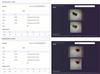 |
Fig. 11 Single-target classification visualization |
 |
Fig. 12 Multi-objective classification visualization |
To verify the adaptability of OpenMV to the practical visual inspection requirements of coal-gangue sorting, validation tests were conducted from three aspects: model size, inference speed, and real-time imaging performance. Given that the MobileNetV2 0.35 neural network was adopted in this study, the trained FOMO model was quantized to INT8 precision. This enables the model to be deployed on the target device in .tflite format, which is then automatically converted to a dedicated format compatible with OpenMV. The final model file size is merely 56 KB, far below the storage upper limit of OpenMV’s built-in memory. This allows for rapid loading and operation of the model without imposing storage pressure on the hardware and avoids the waste of general-purpose computing resources. Actual tests show that the model has an inference latency of 1 715 ms, and the overall system operation frame rate is 38.5 frame/s, which indicates that the acquisition and processing of a single coal-gangue image frame are completed every 26 ms. These results demonstrate that OpenMV fully meets the practical requirements for real-time performance and hardware compatibility in the visual inspection of coal and gangue.
EON™ compiler performance comparison (same accuracy, 17% less RAM, 29% less ROM)
3.2 System Hardware Connection and Performance Test Verification
In the process of constructing the hardware platform, the OpenMV camera was situated in a fixed position at a height of 51 cm and a distance of 53 cm from the iron frame table. The robotic arm was positioned at a distance of 10 cm from the iron frame table, and the conveyor belt was placed in a suitable position. Initially, it is imperative to ensure that the hardware connection is complete. This is necessary to facilitate effective communication between the STM32 and OpenMV components. Secondly, after keeping the light source stable, open OpenMV IDE to run the program and enter the image recognition module to identify the gangue and obtain the pixel position coordinates of the gangue. The master module then receives the position information and converts the pixel coordinate system to the world coordinate system via serial communication. Finally, the actuator performs position solution and trajectory planning to complete the gripping and transfer of the gangue. A physical diagram of the system is shown in Figs. 13-14.
 |
Fig. 13 Overall physical diagram |
 |
Fig. 14 OpenMV recognition diagram |
In the actual testing process, the robotic arm used in the system is a laboratory-grade hardware device, and in order to adapt to its load capacity, the weight of each selected coal or gangue block is controlled between 200-400 g. Setting the conveyor belt transfer speed to 2-3 m/min can reduce the problem of leakage and mispicking. After system commissioning and operation, the communication success rate between OpenMV and the MCU was tested to be 100%, ensuring the reliable and stable transmission of gangue coordinate information. The positioning error range of the robotic arm during gangue grasping is [9,12.5] mm, and the response time from receiving gangue position information to initiating grasping and transfer actions is less than or equal to 0.5 s. These performance metrics fully meet the task requirements for dynamic, small-batch coal-gangue sorting in real-scenario laboratory tests.
The actual robotic arm gripping success rate was then tested. The test results are shown in Table 2. Most gangue can be gripped successfully, with an average success rate of 90.13%, and the overall design requirements can be met. The results show that OpenMV recognition combined with STM32 to control the robotic arm to execute the core logic of sorting coal and gangue is feasible in practice, and also provides technical support for subsequent upgrading of industrial-grade robotic arm and conveyor belt, and other hardware for industrial-grade coal and gangue sorting scenarios.
Test results
4 Conclusion
Aiming at the requirements for lightweight design and high real-time performance in coal-gangue sorting, this study achieves deep integration between OpenMV and STM32, and proposes an intelligent coal-gangue sorting system while elaborating on the functions and corresponding parameters of the hardware involved in the overall system. Based on a self-constructed dataset, this study conducts model training and performance analysis using the MobileNetV2 0.35 neural network, enabling the efficient deployment of the model on OpenMV for accurate coal and gangue recognition. The control board drives the robotic arm’s servos via PWM signals, allowing the robotic arm to accurately locate and grasp target objects; experimental tests were further conducted to verify the feasibility and effectiveness of the proposed system. The system can stably and in real time implement the entire process of coal-gangue identification, grasping and sorting. This sorting method overcomes the limitations of traditional manual sorting, realizes an intelligent coal-gangue sorting approach with high accuracy and low cost, and thus provides a low-cost technical solution for small and medium-scale industrial coal-gangue sorting applications. However, the current design is susceptible to external interference such as lighting conditions and inherent limitations of the hardware devices themselves. Therefore, future research will focus on three key directions: first, adapting the system to diverse working environments and reducing positioning errors by optimizing and improving the recognition algorithms to enhance their adaptability to complex scenarios; second, further optimizing the robotic arm control system to improve the response speed and execution accuracy of control commands. These improvements are expected to promote the system’s adaptation to industrial-grade coal-gangue sorting scenarios.
References
- Wang G F, Liu F, Pang Y H, et al. Coal mine intellectualization: The core technology of high quality development[J]. Journal of China Coal Society, 2019, 44(2): 349-357(Ch). [Google Scholar]
- Wang X W, Liu S G, Wang X S, et al. XR Intelligent operation and maintenance system of coal mine for multi-man-machine complex cooperative task[J]. Journal of China Coal Society, 2019, 49(4): 2124-2140(Ch). [Google Scholar]
- Gao X L. Status and development of intelligent drilling tools for coal mine[J]. Coal Geology & Exploration, 2023, 51(10): 156-166(Ch). [Google Scholar]
- He S R, Yang J K. Practice the concept of green development and build an ecological green mine[J]. China Cement, 2022, 8: 98-101(Ch). [Google Scholar]
- Liang W G, Guo F Q, Yu Y J, et al. Research progress on in-situ intelligent sorting and filling technology of coal gangue underground[J]. Coal Science and Technology, 2024, 52(4): 12-27(Ch). [Google Scholar]
- Miao J. Research and application of intelligent sorting robot for coal gangue[J]. Intelligent Mine, 2023, 4(1): 58-62(Ch). [Google Scholar]
- Eshaq R M A, Hu E Y, Qaid H A A M, et al. Using deep convolutional neural networks and infrared thermography to identify coal quality and gangue[J]. IEEE Access, 2021, 9: 147315-147327. [Google Scholar]
- Liu Y, Si L, Wang Z B, et al. Research progress on coal rock recognition technology based on electromagnetic waves[J]. Journal of Mine Automation, 2024, 50(1): 65(Ch). [Google Scholar]
- Li L J, Fan S X, Wang X W, et al. Classification method of coal and gangue based on hyperspectral imaging technology[J]. Spectroscopy and Spectral Analysis, 2022, 42(4): 1250-1256(Ch). [Google Scholar]
- Zhang Q, Zhang R X, Liu J M, et al. Review on coal and rock identification technology for intelligent mining in coal mines[J]. Coal Science and Technology, 2022, 50(2): 1-26(Ch). [Google Scholar]
- Liu W. Application of Hilbert-Huang transform to vibration signal analysis of coal and gangue[J]. Applied Mechanics and Materials, 2010, 40/41: 995-999. [Google Scholar]
- Tripathy D P, Guru R R K. Novel methods for separation of gangue from limestone and coal using multispectral and joint color-texture features[J]. Journal of the Institution of Engineers (India): Series D, 2017, 98(1): 109-117. [Google Scholar]
- Shang D Y, Huang Y S, Zhang T Y, et al. Design of experimental platform for coal gangue sorting delta robot[J]. Coal Technology, 2023, 42(7): 136-139(Ch). [Google Scholar]
- Cao X G, Liu S Y, Wang P, et al. Research on coal gangue identification and positioning system based on coal-gangue sorting robot[J]. Coal Science and Technology, 2022, 50(1): 237-246(Ch). [Google Scholar]
- Hu P, Li X, Lyu C H, et al. Development of coal gangue separation device based on machine vision for mines[J]. Coal Mine Machinery, 2022, 43(12): 211-213(Ch). [Google Scholar]
- Pang S Z, Li B, Wang X W, et al. Design and experimental research of coal and gangue recognition system based on machine vision[J]. Coal Engineering, 2021, 53(2): 141-146(Ch). [Google Scholar]
- Li S X, Li Y N, Wang Z J, et al. Experimental platform for coal gangue sorting robot based on image detection[J]. Journal of Mine Automation, 2023, 49(7): 107-113(Ch). [Google Scholar]
- Yang Y K, Wang J W, Sun Y Z. Experimental research on object recognition and tracking based on OpenMV vision technology[J]. Control and Instruments in Chemical Industry, 2023, 50(4): 569-572(Ch). [Google Scholar]
- Li H, Zhang Y C, Miao X T. Development of OpenMV intelligent material handling direction[J]. Electronic Technology & Software Engineering, 2022, 11(3): 107-112(Ch). [Google Scholar]
- Xu Y J, Wang Z, Zou J M, et al. Design and implementation of motion target control and automatic tracking system based on OpenMV camera[J]. Modern Electronic Technology, 2024, 47(17): 166-172(Ch). [Google Scholar]
- Zhou W, Yang A S. Research on target recognition system for self-picking orchard fruit basket based on OpenMV[J]. Agricultural Technology & Equipment, 2023, 10: 63-65(Ch). [Google Scholar]
- Wei M C, Li Y, Mao Y L, et al. Design and implementation of garbage sorting robot based on machine vision[J]. Internal Combustion Engine & Parts, 2023, 23: 42-44(Ch). [Google Scholar]
- Boyle L, Moosmann J, Baumann N, et al. DSORT-MCU: Detecting small objects in real-time on microcontroller units[EB/OL]. [2025-03-25]. arXiv:2410.16769. [Google Scholar]
- Wang Z P, Wu Z X, You M L, et al. Color grading detection of cotton based on improved MobileNetV2[J]. Cotton Textile Technology, 2019, 52(6): 15-21(Ch). [Google Scholar]
- Gao L, Liang Z H, Dong H J, et al. Research progress on motion planning technology of intelligent sorting robots for coal gangue[J]. Science Technology and Engineering, 2024, 24(16): 6567-6575(Ch). [Google Scholar]
- Sun L X, Geng Q L, Tang J H, et al. Research on inverse kinematics of redundant manipulator with joint limitation[J]. Modern Manufacturing Engineering, 2022, 8: 46-52(Ch). [Google Scholar]
- Zhang Y H, Pang C H, Song Z H, et al. Research on control method of five degree of freedom manipulator based on OpenMV[J]. Machine Tool & Hydraulics, 2024, 52(5): 1-7(Ch). [Google Scholar]
- Zhang Z. A flexible new technique for camera calibration[J]. IEEE Transactions on Pattern Analysis and Machine Intelligence, 2000, 22(11): 1330-1334. [CrossRef] [Google Scholar]
- Huang G. Binocular vision system realizes the real-time tracking of badminton[J]. Journal of Electronic Measurement and Instrumentation, 2021, 35(6): 117-123(Ch). [Google Scholar]
- Yuan B, Wang H, Li R H, et al. Research on part recognition and grasping method of vision robot[J]. Machinery Design & Manufacture, 2024, 2: 309-313, 318(Ch). [Google Scholar]
All Tables
All Figures
|
Fig. 1 System frame diagram |
| In the text | |
|
Fig. 2 Overall system implementation diagram |
| In the text | |
|
Fig. 3 Hardware structure diagram |
| In the text | |
|
Fig. 4 System workflow chart |
| In the text | |
|
Fig. 5 OpenMV workflow chart |
| In the text | |
|
Fig. 6 Convolutional output feature graph implementation process |
| In the text | |
|
Fig. 7 Mechanical arm model structure diagram |
| In the text | |
|
Fig. 8 Spatial distribution and visualization of coal and gangue sample characteristics |
| In the text | |
|
Fig. 9 EDGE IMPULSE platform training result |
| In the text | |
|
Fig. 10 EDGE IMPULSE platform test result |
| In the text | |
|
Fig. 11 Single-target classification visualization |
| In the text | |
|
Fig. 12 Multi-objective classification visualization |
| In the text | |
|
Fig. 13 Overall physical diagram |
| In the text | |
|
Fig. 14 OpenMV recognition diagram |
| In the text | |
Current usage metrics show cumulative count of Article Views (full-text article views including HTML views, PDF and ePub downloads, according to the available data) and Abstracts Views on Vision4Press platform.
Data correspond to usage on the plateform after 2015. The current usage metrics is available 48-96 hours after online publication and is updated daily on week days.
Initial download of the metrics may take a while.