| Issue |
Wuhan Univ. J. Nat. Sci.
Volume 26, Number 6, December 2021
|
|
|---|---|---|
| Page(s) | 473 - 480 | |
| DOI | https://doi.org/10.1051/wujns/2021266473 | |
| Published online | 17 December 2021 | |
Computer Science
CLC number: TJ391.9
A Communication Method of Distributed Tactical Training Simulation System Suitable for Remote Interconnection
1
Teaching and Research Department of Unit 91976, PLA, Guangzhou 510430, Guangdong, China
2
Operational Laboratory of Naval Command College, PLA, Nanjing 210016, Jiangsu, China
Received:
5
September
2021
Abstract
The traditional distributed tactical training simulation system is limited by the availability and bandwidth of military network transmission channel and does not have the feasibility of remote interconnection and spatial sub-regional deployment. In this paper, a new communication method of distributed tactical training simulation system is proposed to solve the problem of strong business coupling between nodes and system availability under the condition of low bandwidth. The operator of federated exchange, federated queue and their concepts and design requirements are firstly proposed, and the inverted tree, triangle, ring exchange topology and circular queue structure are further constructed. Theoretically, the expected goal of high-speed interworking between nodes in the cluster and high reliable transmission between clusters is realized. The example also shows that this method can significantly improve the throughput of single switching node and federated node after using reliability confirmation mechanism.
Key words: interconnection / distributed system / simulation training / federation / message queue
Biography: LI Gangqiang, male, Master, Senior engineer, research direction: military modeling and simulation, operational training system. E-mail: This email address is being protected from spambots. You need JavaScript enabled to view it.
Foundation item: Supported by the National Natural Science Foundation of China (61401496)
© Wuhan University 2021
 This is an Open Access article distributed under the terms of the Creative Commons Attribution License (https://creativecommons.org/licenses/by/4.0), which permits unrestricted use, distribution, and reproduction in any medium, provided the original work is properly cited.
0 Introduction
Tactical training simulation system, composed of a series of interconnected functional subsystems, can meet the practical needs of military tactical training and improve the training effects. Considering the flexibility, practice and users, the distributed architecture is the first choice for system developers and the perfect designing guide of remote interconnection. Remote interconnection mainly studies and solves two kinds of problems: one is the method of information transmission, which focuses on the reliable data transmission theory, loss and duplication solution in the process of data transmission [1-3]; the other is to study how to use various network components to build channels to improve bandwidth and reliability as much as possible[4,5]. With the continuous improvement of network speed, the gradual increase in the reliability of network communication equipment and the wide use of application layer message middleware, remote interconnection has currently played an important role in smart cities, intelligent communities, Internet of Things and mobile APPs[6-8].
The particularity of the tactical training simulation system in the aspects of user, data confidentiality, transmission path, message content, as well as the low bandwidth and instability of the transmission channel have restricted the application practice of remote interconnection for a long time. In recent years, with the continuous improvement of military communication infrastructure, the stability of long-distance low-bandwidth communication links has been solved. Based on the existing communication links, the communication methods between multiple functional subsystems deployed in different places are studied to solve the problems of network delay and channel congestion caused by message reply confirmation under long-distance transmission. Thus, the distributed tactical training simulation system can really transfer from small area intranet deployment to remote wide-area connection, and from centralized application to distributed federation.
1 Problem Analysis
Suppose the tactical training simulation system M consists of n functional subsystems called clusters. Clusters form a federated structure through network links. Each cluster is divided into some real user seats according to business functions, which are recorded as nodes. The node uses the message response mechanism to ensure the reliable transmission of the information sent or received. According to the actual needs, nodes of the M-System can be deployed in one place, multiple places or a combination of one and multiple places. When all nodes are deployed in one place, the message transmission rate is high, and the bandwidth cost of node message confirmation can be negligible. The M-System can also be deployed in many places. Many countries often use this method to train team cooperation, but its application in China is limited because the military standard of wireless sensor is not clear. The last combination means that nodes in the cluster are deployed in the same place, interconnected through the local area network, whereas clusters are distributed in different places and bridged by low-bandwidth links. In this mode, the messages between the nodes can interact with each other at a high speed in the local area network, but the message response speed between the remote nodes is slow, which may cause network channel congestion. Message communication mechanism based on the remote interconnection need to be focused in such background.
As shown in the Fig. 1, suppose the M-System consists of three clusters. The Cluster-1 consists of i-1 nodes and is deployed at Site A; Cluster-2 consists of k-i nodes and is deployed at Site B; Cluster-3 consists of n-k+1 nodes and is deployed at Site C. The nodes in each cluster are connected by high-speed Ethernet, and three clusters are bridged by low-bandwidth communication links. A proper and excellent message transmission method needs to be designed to meet the following goals.
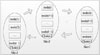 |
Fig. 1 Theoretical structure of M-System |
① Among nodes in one cluster, the data transmission speed is as fast as possible and the information confirmation delay is as small as possible.
② The information confirmation delay between any two clusters is as low as possible.
③ All clusters can support concurrent operations, and further internal and external operations do not interfere with each other.
④ When the visiting number of node clients increases sharply, clusters will not collapse under sudden overloaded requests.
2 Communication Operator Design
The data passed between clusters are called messages. The communication operator represents the highly reliable message delivery service provided by the components responsible for the communication on the TCP/IP protocol network layer or transport layer, and can realize platform-independent data interoperability[9,10]. The combination of communication operators can constitute the message delivery process and communication model, which has been proved to realize the effective communication in distributed environment[11-13].
2.1 Single Exchange and Single Queue
The exchange operator is a component that receives data, similar to a mailbox. It is responsible for receiving messages from the sender and delivering them to the queue according to certain rules. If the destination queue cannot be found at the time of delivery, the message will be returned to the sender or discarded directly, as shown in Fig. 2. A queue, which is a physical carrier that stores messages, establishes a connection with the exchange through binding keys, and receives messages delivered by one or more exchanges.
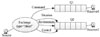 |
Fig. 2 Structure of single exchange and single queue operator |
Definition 1 The path identification between the queue and the exchange is called the binding key representing the rule basis on which the exchange distributes data.
Definition 2 The routing key is the identity of the data sent by the sender and represents the destination queue expected by the sender.
According to different message delivery requirements, three different exchange rules need to be designed.
Rule1: Fanout, the broadcast rule. This type of exchange can route received messages to all queues bound to itself.
Rule2: Direct, the one-to-one rule. This type can only deliver messages to queues with the same queue routing key and sender binding key.
Rule3: Topic, the pattern matching rule. This exchange rule is responsible for routing messages to queues where the queue’s routing key and the sender’s binding key is matched under the matching pattern.
Broadcast messages such as the military forces operation seat status, system control instructions, situation within the M-System can be classified into fanout-type (represented by F). Messages transmitted among the force operation seats and the commanding instructions can be assigned to direct-type. Topic-type is mainly used in the replaying function subsystem, evaluation subsystem and so on, which needs to receive multiple sender messages.
The destinations of messages are determined by direct-type exchange and topic-type exchange by binding keys and routing keys. Direct-type exchange chooses one queue with equal binding keys and routing keys for delivery. To further meet the one-to-many delivery needs, two special character identifiers “*” and “#” are used, where “*” represents one word and “#” represents zero or more words. The binding key and routing key use “.” as the delimiter[11].
The working process of the topic-type exchange is shown in Fig. 3.
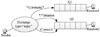 |
Fig. 3 Topic-type exchange |
Messages with routing key=“control.command. situation” are delivered to queues Q1 and Q2 at the same time.
Messages with routing key=“control.hidden.situaton” are only delivered to queue Q2.
Messages with routing key =“test.command.situaiton” are only delivered to queue Q2.
Messages with routing key =“control.command. demo” are only delivered to queue Q1.
When an exchange (a queue) is not coupled with other exchanges (queues) or has direct interaction with data, the exchange is considered to be a single exchange (a single queue). When the single exchange and the single queue are applied to the M-System and deployed in the same cluster, the respond speed of the M-System can be effectively improved. Therefore, goal ① is satisfied.
2.2 Federated Exchanges and Federated Queues
The federated exchange can receive messages forwarded by upstream exchange and also redeliver the messages originally sent to the upstream exchange to the local queue. The federated queue allows a local consumer to receive upstream queue messages. The upstream exists in the design, which is completely transparent to the sender and receiver, and the actual physical location of the exchange and queue can be ignored. Users only need to care about the destination of the message and the business processing relationship, regardless of the federation creation process. Remote deployment does not make a difference in users’ experience.
Suppose the two federated nodes are node(1) and node(3). Node(1) sends a message to node(3) and waits for an execution confirmation. In the traditional communication method, the message is sent by direct post road, and the sender needs to wait for the other to answer. Node(1) will have long time delay. The transmission of messages is inefficient and easy to be blocked. The new communication method is to establish a federated map between node(3) and node(1). When the sender delivers the messages to exchange AMQP (EA) in the normal way, node(1) can directly send the confirmation receipt. The federated mapping can generate an anonymous queue to receive messages from EA. The receiver can consume anonymous queue messages in real time through EA. The message exchange process is shown in Fig. 4.
 |
Fig. 4 Federated exchanges and federated queues |
In such mode, the client can quickly send a message and receive a confirmation receipt, and then the message is forwarded to the exchange of node(3) over the federated link and eventually stored in the queue bound to it. The federation is beneficial to both the sender and receiver of the message, and it also transfers traditional message from the remote to local message, which eliminates the network delay caused by long distances.
3 Federal Structural Design
Taking the above communication operator as the basic component, a federated communication structure of the M-System suitable for remote interconnection is established. The federated communication structure can well achieve message delivery between federated nodes in different clusters, tolerate unstable network connections, and is compatible with single and federated exchanges and queues. It can better attain the goals ②-④.
3.1 Exchange Topology
The federated exchange is a special single exchange. A new single queue can be created to bind to the old federated queue, represented by “X”. Messages sent by the client to the federated exchange have equal chances to be received by the federated consumer or sent to a single queue. As a result, load sharing can be achieved.
The M-System is mainly composed of model service subsystem, situation fusion subsystem, situation display subsystem, force control subsystem, guidance and adjustment control subsystem, message service subsystem and so on. According to the information exchange and transfer requirements of each functional subsystem, three typical exchange topologies are given below.
1) Inverted tree structure
The main feature of the inverted tree structure is that the message sender is unique. As shown in the Fig. 5, the message starts from the sender step by step, layer by layer, and finally reaches the lowest consumer. This topology is mainly applied to the guide and adjustment control subsystem and the model service subsystem. The commander sends messages such as various guidance and adjustment control instructions, situation updates and ammunition resupplies to the subsystems.
 |
Fig. 5 The inverted tree exchange topology |
Because there are many federated nodes involved, this structure needs to use on-publish mode to ensure that even if the network transmission fails, the message will not be lost.
2) Triangular structure
This structure is suitable for the situation where the three functional subsystems are federated by each other. The EA of any two nodes are upstream to each other, as shown in Fig. 6. The operational relationship of the force control subsystem, the situation mapping and display subsystem and the command and control subsystem within the one military unit is represented by this topology. Suppose node(1) represents the command and control subsystem, node(2) represents the force control subsystem, and node(3) represents the situation mapping and display subsystem. First, node(1) sends command and cooperative action requirements to node(2), and node(2) feeds back the command execution status to node(1). Then, node(2) sends the real-time location of the target and the behavior state of force equipment to node(3), and node(3) sends geographical environment information to node(2). Lastly, node(3) requests the plotting operation from node(1), and node(1) feeds back the plotting requirements to node(3).
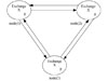 |
Fig. 6 The triangular exchange topology |
3) Ring structure
It is similar to the token network structure. It allows messages to flow sequentially on the federated node and realizes the balanced load distribution of the message on the ring federated node, as shown in Fig. 7. The location of the sender determines the other in which messages flow, so the closer you get to the sender, the greater the EA of the federated note will bear the load.
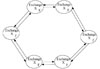 |
Fig. 7 The ring exchange topology |
In order to avoid message loops, the number of flow hops of the ring topology must be set. It is generally equal to the number of federated nodes of the ring minus 1. After the calculation response from the model function subsystem is transferred sequentially by the command and control subsystem and the force operation subsystem, it finally returns to the origin. This message flow structure is a typical ring exchange topology.
3.2 Queue Structure
The federated queue structure can balance the load of a single queue by cooperating among multiple nodes (clusters). A federated queue can connect to one or more upstream queues and obtain messages from these queues to meet the needs of local consumers. It can also co-exist in the same federated node with a single queue, as shown in Fig. 8.
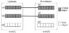 |
Fig. 8 The federated queue structure |
Suppose Queue Q1 and Q2 are located in federated node(2), and their federated queues of the same name are established in federated node(1) for load sharing. When a consumer connects to node(2) and requests to obtain messages, if there is message accumulation in Q1(Q2), these messages will be first consumed. If Q1(Q2) is empty, the messages in the upstream queue of node(1) will be actively pulled and stored locally for consumption. The client can consume both the queue of node(1) and the queue of node(2). This distributed queue deployment can increase the capacity of a single queue. If the consumers in Q1 do not have time to consume the messages in the queue, the consumers deployed in node(2) can share the consumption for them.
The federated queue supports unlimited cycle forwarding, and the messages in the queue can be obtained by local consumers or consumed by remote federated nodes. In other words, the consumption sent by one part will switch back and forth in different federated queues.
4 Example and Performance Analysis
4.1 Example
Testing environment: There are 13 computers with the same hardware configuration (CPU: 8 cores, dominant frequency: 2400Hz, memory: 32GB, hard disk size: 1TB). Every three computers are set as a cluster, and a total of three clusters are set up. The computers of the cluster are interconnected with a gigabit network. Two 10-megabit switches are bridged between clusters to simulate remote networks. In order to simulate the network bandwidth instability which is easy to occur in the communication link when interconnected in different places, the remaining four computers are used as jammers. Every two computers are connected to a 10-Mb switch as a group, sending data of different sizes in the experiment process, simulating to occupy the bandwidth from time to time. Each cluster randomly selects a computer as a federated node to access a 10-Mb switch, as shown in Fig. 9.
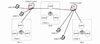 |
Fig. 9 An example of the remote interconnected M-System deployment environment |
Experimental index: throughput of node in per second[15].
Experimental step: 1) Within a certain period of time, the throughput of a single switching node in a single cluster adopts the reliability confirmation mechanism. 2) Experimental object is changed to the federated node.
4.2 Performance Analysis
1) The throughput of a single switching node in the cluster
Take Cluster-1 deployed in site A as the experimental object. For federated node(1), create two message senders, one is in node (1) and the other is in node(2). Sent the data(size: 1 KB, 1 MB, 10 MB) 10 times at the same time, and each lasts for one min uninterruptedly. Record the throughput of a single switching node after using the reliability confirmation mechanism. The result is shown in Fig. 10.
As shown in Fig.10, three single exchanges, EA-1K, EA-1M and EA-10M, have been created in the node, and bounded to the queue_capacity-1K, queue_ capacity-1M, queue_capacity-10M. Under the preset experimental method and data set, if reliability confirmation mechanism is adopted, the data transmission rate and the received confirmation response rate are the same, with an average of 14 Kb/s. In the high-speed LAN environment, when the data scale is small, the throughput of single channel is also the same, and the transmission rate of messages is stable. The message received by the queue shows that the smaller the capacity of a single message is, the more opportunities it has to receive and process the response (Fig. 10(d)).
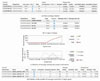 |
Fig. 10 Experiment results of throughput of a single node |
2) The throughput of the federated node
Based on Experiment 1, establish federated exchanges and federated queues for node(1), node(4) and node(7). Create message senders, make the two jammers work, and send the data(size:1 KB, 1 MB, 10 MB) 10 times at the same time, and each lasts for one min without interruption. Record the throughput of the federated node after also using reliability confirmation mechanism. The result is shown in Fig. 11.
 |
Fig. 11 Experiment results of throughput of federated nodes |
From the above experimental result, it can be concluded that the establishment of federated nodes can overcome the bandwidth limitations of remote backbone networks. Continue to send messages according to the original method, and the rate of sending and receiving acknowledgements in the federation system has not been decreased, and the response rate for the sender remains unchanged, showing a good high-speed transmission performance. On the other hand, the total amount of messages received by the federated queues decreases slightly, but they can meet the needs of consumers in different sites and maintain high reliability.
5 Conclusion
The M-System simulates the tactical engagement process in modern warfare by building network simulation environment. The mode of communication affects the structure of the M-System and the deployment of each functional subsystem. In the past, subject to the networking environment, distributed M-System cannot really be distributed in different sites. Nowadays, with the improvement of military communication infrastructure and the establishment of new communication models, remote interconnection can become a reality and greatly innovate military training. In the next step, the mirroring and partitioning methods of federated nodes will be studied to improve the robustness of asynchronous data exchange.
References
- Huacarpuma R C, de Sousa Junior R T, de Holanda M T, et al. Distributed data service for data management in Internet of Things middleware [J]. Sensors, 2017,17: 1-25. [Google Scholar]
- Dave B, Buda A, Nurminen A, et al. A framework for integrating BIM and IoT through open standards [J]. Automation in Construction, 2018, 95: 35-45. [Google Scholar]
- Sallow A B. Design and implementation distributed system using Java-RMI middleware [J]. Academic Journal of Nawroz University, 2020, 9: 113-120. [CrossRef] [Google Scholar]
- Fersi G. Study of middleware for Internet of healthcare things and their applications [C]// 2020 International Conference on Smart Living and Public Health. Berlin: Springer-Verlag, 2020: 223-231. [Google Scholar]
- Rosa N, Cavalcanti D, Campos G, et al. Adaptive middleware in go—A software architecture-based approach [J]. Journal of Internet Services and Applications, 2020, 11(1): 1-23. [CrossRef] [Google Scholar]
- Qu W Q, Zhou C L, Zhang Q, et al. Scheme of IoT middleware based on message service [J]. UPB Scientific Bulletin Series C, 2019, 81(1): 16-26. [Google Scholar]
- Atzori L, Iera A, Morabito G. The Internet of Things: A survey [J]. Computer Networks, 2010, 54: 2787-2805. [Google Scholar]
- Nguyen C N, Lee J, Hwang S, et al. On the role of message broker middleware for many-task computing on a big-data platform [J]. Cluster Computing, 2019, 22: 2527-2540. [Google Scholar]
- Celar S, Mudnic E, Seremet Z. State-of-the-art of messaging for distributed computing systems [J]. International Joural of Vallis Aurea, 2017(3): 5-18. [Google Scholar]
- da Cruz M A A, Rodrigues J J P C, Lorenz P, et al. In.IoT—A new middleware for Internet of Things [J]. IEEE Internet of Things Journal, 2021(8): 7902-7911. [CrossRef] [Google Scholar]
- Yuan Z H, Pang B W, Du Y K, et al. Design and implementation of Internet of Things message subscription system based on Kafka [C]// 2019 IEEE 11th International Conference on Communication Software and Networks (ICCSN) Conference. Washington D C: IEEE Press, 2019:12-15. [Google Scholar]
- Liu Y, Li D, Zheng C D. An improved underwater confrontation simulation method of naval amphibious operational training system [J]. Wuhan University Journal of Natural Sciences, 2018, 23(3): 225-229. [CrossRef] [Google Scholar]
- Liu Y, Wen J Y, Ji D Q. Integration of naval distributed tactical training simulation system based on advanced message queuing protocol [J]. High Technology Letters, 2016, 22(4): 385-394. [Google Scholar]
- Liu Y, Song J, Wen J Y. An optimizing algorithm of static task scheduling problem on hybrid genetic algorithm [J]. High Technology Letters, 2016, 22(2): 170-177. [Google Scholar]
- Dobbelaere P, Esmaili K S. Kafka versus RabbitMQ: A comparative study of two industry reference publish/subscribe implementations: Industry paper [C]// The 11th ACM International Conference on Distributed and Event-based Systems. New York: ACM, 2017: 227-238. [Google Scholar]
All Figures
|
Fig. 1 Theoretical structure of M-System |
| In the text | |
|
Fig. 2 Structure of single exchange and single queue operator |
| In the text | |
|
Fig. 3 Topic-type exchange |
| In the text | |
|
Fig. 4 Federated exchanges and federated queues |
| In the text | |
|
Fig. 5 The inverted tree exchange topology |
| In the text | |
|
Fig. 6 The triangular exchange topology |
| In the text | |
|
Fig. 7 The ring exchange topology |
| In the text | |
|
Fig. 8 The federated queue structure |
| In the text | |
|
Fig. 9 An example of the remote interconnected M-System deployment environment |
| In the text | |
|
Fig. 10 Experiment results of throughput of a single node |
| In the text | |
|
Fig. 11 Experiment results of throughput of federated nodes |
| In the text | |
Current usage metrics show cumulative count of Article Views (full-text article views including HTML views, PDF and ePub downloads, according to the available data) and Abstracts Views on Vision4Press platform.
Data correspond to usage on the plateform after 2015. The current usage metrics is available 48-96 hours after online publication and is updated daily on week days.
Initial download of the metrics may take a while.